Analysis of residual error and their consequences in CANopen systems
Residual error analyses for CAN networks have been performed for years. It is well documented, that commonly used equations do not fully apply for analytic computing of the residual error probability of CAN networks. Also too high bit error probability values have commonly been used in the analyses. Furthermore, CANopen networks have been analyzed as CAN networks, without taking into account the additional safeguards provided by various CANopen services. Results have been very pessimistic, which has lead to significant unnecessary cost and complexity in various applications.
This paper presents a complete analysis for CANopen communication, based on the most commonly supported services without dedicated safety extensions. The analysis for CAN communication is based on widely accepted equations and parameter values. In addition to the CAN communication, effect of the most commonly supported CANopen communication services will be analyzed. Some improving factors needed to be neglected to keep the analysis understandable. Main result is that CANopen offers significant improvement in dependability of the communication by filling the gaps of CAN layer. CANopen provides several magnitudes higher dependability than the analog instrumentation. After analysis, some solutions to reduce effectiveness of residual errors are listed, most of which are introduced in various device profile.
Introduction
Residual error analyses for CANopen networks has been made for years, but error detection performance of CAN communication has been underestimated in most analyses. In addition, bit error rate has typically been estimated too high and CANopen networks have been considered as raw CAN networks – all safeguards provided by CANopen have been neglected.
The most significant result of traditional approach has been an increased complexity caused by additional, application layer safety implementations. Another result has been common misunderstanding, that network communication was less dependable than analog signalling.
LSS and SDO protocols use request-reply approach, where individual corrupted messages cannot lead into misbehaviour. An invalid request looking as a valid request for server device will result inconsistent reply. A request, which has been redirected into invalid server device, will result reply from invalid device.
Corrupted reply will be inconsistent with the request, which will also be noticed. At least two complete download transaction will be needed for permanently invalid parameter changes. First one will be required for setting value either into invalid device and valid object or into valid device but invalid object. Second one will be required for storing the change into nonvolatile memory. Successful invalid operation requires, that referenced object has same data type than the original object. The value to be written shall also be within the allowed range. Therefore, analysis presented in this paper concentrates on the one-to-many CANopen protocols – heartbeat, emergency, SYNC, TIME and PDO.
This paper starts with a short review of the analog signalling to provide reference for dependability of CAN communication. Then, a residual error model is presented to describe the approach behind the analysis. Analysis presented in this paper concentrates on the distribution of masquerade and corruption errors. Further remarks are pointed out and further activities are proposed in discussion. Finally the conclusions are set.
Analog instrumentation as a reference approach
4 to 20mA current loop is de-facto in many industry areas and therefore it is used as a reference in this article. Sensor failures as well as sensor condition monitoring is based on signal value going out of range, either below 3.5mA or over 20.5mA. As long as the signal value remains within the nominal range, despite of additional resistance or conductance, failures cannot be detected by consuming device. Only full break of each line and short-circuit between each two signal lines can be detected. Each failure causes continuous effect for signal and furthermore potentially faulty system behaviour. Diagnostics coverage clearly falls into category “none” used in the safety standards.
It is clearly stated, that analog signals shall also be analysed, typically as an integral part of sensing or actuating subsystems. Furthermore, it is clearly stated that a well-tried component for some applications can be inappropriate for other applications. The statements unambiguously define, that control systems shall always be comprehensively analysed, independent of the used technologies. If certain faults or failing components are excluded, exclusions shall be justified by results of analyses.
Residual error model for CANopen communication
Communication errors can be divided into standard categories. Standard CANopen communication services provide safeguards against most categories. Deletion, corruption and timing errors can be revealed by time-out monitoring of received frames – e.g. heartbeat consumer and RPDO time-out monitoring. Repetition can be managed only in producing nodes by managing carefully transmission type, inhibit and event times. Structural inconsistency can be revealed by heartbeat consumer but signalling inconsistency and insertion can be avoided only by careful system design, for which CANopen defines management process and file formats.
Incorrect sequence applies only for LSS and SDO protocols, where request/reply approach together with transaction type specific states enables detection of both single frame and sequence errors, which may vary according to the used accessing mode. Addressing issues in CANopen networks are solved by the design process and proper design tools.
In addition to the standard error categories, residual errors – errors which cannot be detected by CAN controllers and CANopen protocol stack – have been separated into an additional category. The residual errors are divided further into three categories, depending on which fields of the frame are corrupted. CRC error occurs, when only a CRC field is corrupted. This category is considered as impossible. However, if this category were possible, it would not effect on the CAN-ID or signal values and could be neglected.
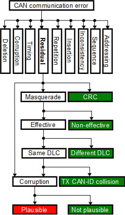
Figure 1: Residual error model
Corruption error exists, if there is at least one corrupted bit in the data and CRC fields, but not in the CAN-ID field. If only a smaller range or limited set of values of the signal are used, application level plausibility checking may detect portion of the errors. CANopen system management process enables efficient and reliable parametrization of corresponding checking functions.
Masquerade error means, that at least one bit in the CAN-ID field is corrupted. There may be other corrupted bits in other fields, too. Typically a small subset of the available CAN-IDs are used for communication, which significantly reduces the possibility that corrupted CAN-ID is used by other services. Consumers of the frame with original CAN-ID detect the masqueraded frame as deleted, typically based on time-out monitoring. Different protocols use different number of data bytes and also number of data bytes in different PDOs may vary. RPDO mapping in consuming devices will reveal the frames having too few data bytes. If devices support monitoring of the CAN-IDs used by they own, they can indicate if other devices transmit frames with reserved CAN-ID. If both CAN-ID and DLC of the corrupted frame are valid, masquerade errors become effective and the final effect is corruption of at least one signal.
A simplified residual error model is illustrated in figure 1. Residual error categories not introducing a risk are marked green. Masqueraded messages which are not detected, result corrupted signal values. If corrupted signal values are out of range or not equal to the allowed values, corruption can be detected. If corrupted signal value cannot be detected by plausibility checking, the corrupted value is passed through. Such category is marked as red, because it is the final appearance of both corruption and masquerade residual errors. It is noticeable, that effect of any residual error in digital communication is temporary, because it will be updated in the next transmission cycle. Single residual error is dangerous only, if single corrupted sample can introduce a safety risk.
Effect of errors in different fields
Errors in control field can be divided into three categories – don’t care, errors that do not affect on the frame length and errors that affect on the message length. Reserved bit R0 of control field is handled as don’t care by receiving devices. Furthermore, the last bit of endof- frame is handled as don’t care, because there is no time left for signalling the error. Because the fields are handled as don’t care, they need not to be included in the analysis.
Fields RTR, IDE and DLC affect on the message length. If RTR bit is recessive, data bytes are not included and DLC indicates the number of bytes in the requested message. If IDE bit is recessive, an extended ID is included before the rest of the control field. DLC defines the number of data bytes included in the message. Depending on the bit error, it can either increase or decrease the message length.
If a receiver expects longer message than transmitted, stuffing error occurs. Acknowledge delimiter and 6 first bits of end-of-frame form a stream of 7 or 8 recessive bits in the end of transmission violate the stuffing rule. If a receiver expects shorter message than transmitted, form error occurs. Form error may be caused by transmitted acknowledge slot, CRC or DATA fields, depending on the difference in the lengths of transmitted and received message.
Corruption of RTR or IDE bits or DLC field always lead to difference more than one byte, which will lead to reliable detection of an error. Message length difference less than one byte may be caused by misinterpreted stuff bits and several additional corrupted bits are needed to get the CRC checksum matching the corrupted message contents. It is also required, that each device in the network receives similarly corrupted message not detected erroneous. Thus, RTR and IDE bits and DCL field need not to be included in the analysis.
In addition to ID, DATA and CRC fields, errors not affecting on the message length may exist in acknowledge field and end-offrame. Errors in acknowledge slot and acknowledge delimiter are interpreted respectively as acknowledge and form errors and solved by automatic retransmission. Thus, the analysis can focus on errors in ID, DATA and CRC fields.
Residual masquerade and corruption errors
The basis for the presented analysis has already been published and the analysis in this paper increases the accuracy by presenting the distribution of corruption and masquerade residual errors.
As in the earlier analyses, following assumptions have been made:
- Bit errors are independent of each other
- A frame with single bit error will always be detected
- Each device is in error active mode
Denote the length of ID field by NID the length of DATA field by NDATA and the length of CRC field by NCRC. Further denote the bit error probability by p, a and b define the range of error bits, where b ≥ a ≥ 2.
Total (non observable) residual error probability can be written as:

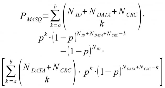
Probability of (non observable) masquerade error can be written as:
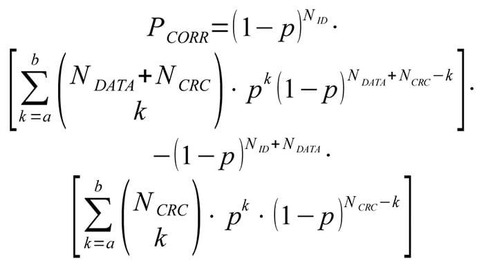
Probability of (non observable) corruption error can be written as:
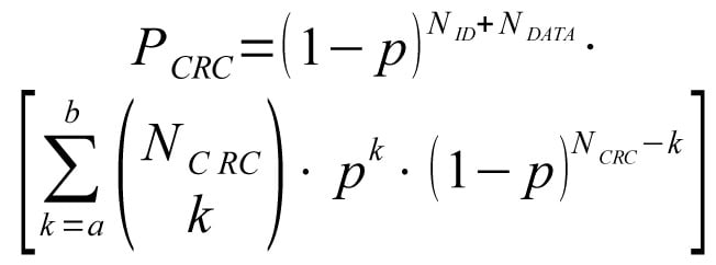
Probability of (non observable) CRC error is:
Relative proportion of masquerade errors:

Relative proportion of corruption errors:

Now consider the cases with given range of error bits. The bit error probability p=3.1×10⁻⁹, ID field length NID=11 and maximum number of data bits NDATA=64 are used in the calculations. The length of CRC field, NCRC is fixed to 15 bits.
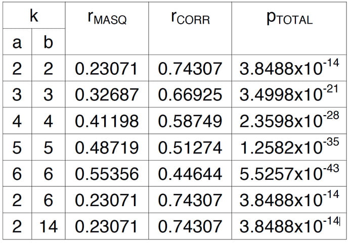
Table 1: Distribution of masquerade and corruption errors versus number of corrupted bits
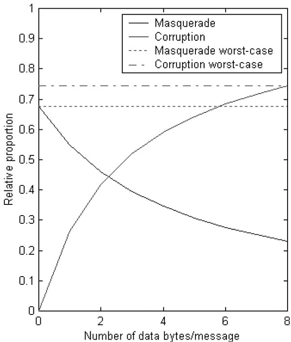
Figure 2: Distribution between masquerade and corruption vs. DLC
The distributions are summarized in table 1. Total (non observable) corruption probability pTOTAL gives an idea, how significant the distribution category is. It can be seen that by accuracy of given 5 significant numbers, there is no difference in error type distribution between cases b=2, b=6 and b=14 when a=2.
If single values are used for average DLC, in the worst-case 67.8% of the residual errors are masquerade errors and 74.3% corruption errors according to figure 2. Especially the masquerade error probability is pessimistic, because typically only 5% to 10% of the all available IDs are in use. Thus, residual corruption error probability according to the average DLC could be used instead.
Putting all together
More realistic bit error probabilities based on measurements have already been published. Long practical experience on mobile machines have confirmed the validity of the values for average electromagnetic environment. Message error probability PME can be computed from biterror probability p and number of bits in a message NBitsInMsg by equation 7 and residual error probability PRES from message error probability by equation 8.
Equation 9 presents, how the effective residual masquerade error probability PMasEff can be computed from residual masquerade error probability PMas, number different messages in use MInUse and number of bits in the ID-field NID. It is still pessimistic, because it has been kept simple and independent of the actual bitpatterns.
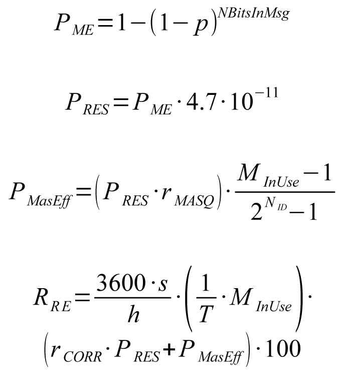
It is assumed that the relative distribution between non-observable error cases caused by corrupted bits remains the same in the perceived residual error distribution. The number of corrupted bits varies from a to b, where b ≥ a ≥ 2.
When equations 7 to 9 are combined with the previously computed distribution, magnitude for the effective residual corruption error probability for full-loaded 1Mbps network can be calculated. Transmission interval T is assumed to be 10ms, which is common in control systems. At given update interval, maximum number MinUse of different full length messages with maximum number of stuff bits is 66. Finally, the sum of effective residual corruption and masquerade error probabilities is converted to probability of errors per hour RRE according to equation 10. Because only 1% of the total error budget is allowed for network communication, the raw value need to be finally multiplied by 100.
Equation 10 results with given values 3.6524×10⁻⁸ errors/hour, when the worstcase values rMASQ=67.8% and rCORR=74.3% are used. The result is interesting, because maximum allowed probability of dangerous failures per hour (PFH) value for SIL3 is 10-7 errors/hour.
One should notice, that the computed values are still quite pessimistic. Network was assumed to be full-loaded in the example scenario, but typical network utilization is much below 100%. It was also assumed that all messages have maximum number of potentially corrupted bits due to bit-stuffing, but the positive effect caused by lower number of data bits was neglected. Bit error probability decreased by higher number of nodes in a network was neither considered in the example scenario.
It is common approach in the timetriggered systems, that each SW function shall tolerate single missing or invalid update. It has been assumed, that biterrors are independent. Thus, the rate of two consecutive invalid updates caused by the residual errors is 5.6144×10⁻²⁵ per hour in average error conditions. The 1 % portion of the total failure rate for network communication has been used.
Changes in CAN FD
Though residual error rate of CAN seems to be low, some improvements have been included in CAN FD. Fault tolerance of bit-stuffing mechanism has been improved by including the stuff-bits into CRC checksums. Another improvement is the use of fixed stuff-bits in the CRC field. Those improvements cover the problems caused by corrupted stuff-bits. Longer CRC codes have been introduced for maintaining the Hamming distance despite of higher number of data bits per message.
The change of RTR bit into reserved makes the bit as don’t care. It is not any more possible to detect corruption of the RTR bit by calculating the number of data bits and comparing it with the value of RTR bit and DLC field. Residual errors in DLC may be revealed more accurately, because all bit patterns together with state of the EDL bit result different number of data bytes.
Discussion
While corruption of a single CAN message introduces only a temporary deviation to a signal value, typical errors in analog cables introduce permanent deviation relative to typical signal change rate. In CAN based systems, the temporary deviation is typically corrected by next update. In case of permanent error, messages cannot transmitted through the CAN network, which can be monitored. In analog systems, permanent errors can be detected only, if the signal value range is exceeded.
Physical layer deviations affect directly on the bit error probability. Therefore it is important to take into consideration also the physical layer quality. Based on the experience, special attention shall be paid for implementing the designed quality in the system assembly and maintaining it during operation and service. Otherwise the realized dependability may differ from the designed dependability, which violates the functional safety requirements.
The analysis revealed possibilities to interesting, simple application layer safeguarding design practices to decrease the residual error probability without adding complexity:
- Using standardized, high quality cabling components to keep the quality level according to the requirements.
- Avoiding topology deviations and using active topology components, when other than linear structure is required.
- Selection of the CAN-IDs of cyclically transmitted messages so that there exist difference of at least 2 bits. If default connection set need to be used, node-IDs may be organized accordingly.
- If CAN-IDs cannot be fully reorganized, different DLCs may be used for messages with only one bit difference in CAN-ID.
- Intentional mapping of all signals from RPDOs to either signal or application layer dummy objects increase the error detection capability provided by of RPDO mapping.
- Each application programmable device may provide parallel, spatially distributed, application layer monitoring by receiving all signals from the network.
- The use of update cycle double of the required to keep the effect of single corrupted value update and design of filters and controllers so that they tolerate single missing or corrupted value updates without significantly degraded operation.
- The use of enumerated values with difference of more than 2 bits as much as possible.
- Distributing the functions rather than centralizing, because increasing the number devices in a network increases error detection performance.
Many CANopen safeguards expect systematic management of design information as well as found design practices improving the effect of the safeguards. It is essential to follow the standardized system design process and information storage formats to minimize the deviation between designed, implemented and maintained quality in system configurations.
Absolute worst case values have been used in the analysis. Reduction of update cycle and number of used messages may enable reaching either higher SIL class or same SIL class but in worse EMC conditions. Using absolute worst case values instead of realistic values for current system and environment everywhere will lead significant design overhead.
In the future, it would be interesting to compare the dependability provided by SRDO protocol with the dependability achievable with the use of standard PDO protocol with direct and inverted signals and carefully selected CAN-IDs. The significance of masquerade errors is still overestimated. It would be interesting to analyze, how big improvement the bit pattern based analysis will reveal.
Conclusions
Any CAN based implementation is not perfect, but CANopen communication is several magnitudes more reliable than analog communication. To improve overall dependability of control systems, sensor and actuator connections should first be updated from analog to CANopen.
After the upgrade of communication dependability, application SW quality becomes the weakest point, not communication.
Residual error rate of a single CANopen network can meet requirement of SIL3 in average error conditions, but if single faulty update can be tolerated by filters and controllers, residual error rate of CANopen networking is not a limiting thing to any SIL level.
CANopen provides significant safeguards the top of CAN. Therefore CANopen networks cannot be analysed as pure CAN networks as has been done in earlier analyses. The effect of CANopen safeguards can be improved by following design principles used e.g. in CANopen safety. Earlier analyses have also been overestimating the significance of masquerade errors.
The major bottlenecks of CAN error detection mechanisms have been solved in CAN FD. Furthermore, Hamming distance will be maintained despite of higher number of data bytes, which will keep CANopen competitive integration platform for machine control systems. Physical layer and system configuration shall be systematically designed to enable the systems meet the designed dependability. Systems shall be designed, assembled and serviced according to the standardized process to implement and maintain the intact physical layer and consistent system configuration.
There are not enough detailed and public failure information available, which has made it difficult to find correct failure information from the literature. One option could be, that CiA will organize a communication forum for exchanging safety and dependability related information.


