CAN Topology Improvements for an Energy Storage Site
TK Engineering Oy collaborated with a customer with the goal of improving their control system CAN communication implementation. The scope of the work was focused on the control systems CAN topology. Based on the initial system state an improved CAN topology was designed. With proper topology design choices and the use of CAN switches the system reliability and future-proofness was increased.
Network topology pre-study
Based on the initial state of the system a pre-study was created. The goal of the pre-study was to identify potential vulnerabilities in the control system CAN topology implementation. Based on the pre-study findings a draft for CAN topology improvements was made. With the use of CAN switches the CAN topology was enhanced to increase reliability and future-proofness of the system. By utilizing the existing cabling of the system, the CAN topology was changed from a star-like topology to a segmented one.
Segmented CAN bus topology
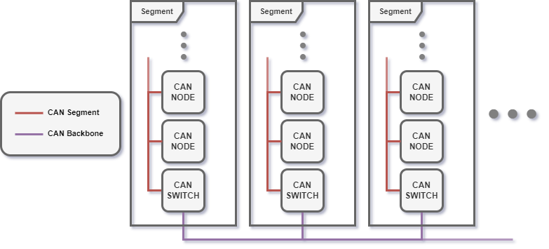
The improved CAN bus implementation employs a segmented CAN bus topology architecture. Extended CAN bus lines are divided into modular sections and connected together using a CAN backbone line. This notion is displayed in the figure below.

Figure 1: Segmented CAN network topology
With the use of CAN switches, the network topology can be flexibly adapted to different use cases. The use of CAN switches enables the implementation of star like topologies with linear CAN segments. With the use of CAN switches, CAN network topology design benefits from the flexibility of star-like topologies and the reliability of linear topologies. Also, by dividing the CAN network into segments, the total length and bandwidth of the system can be increased. Different network sections can be run with different bitrates to increase the section’s maximum length or bandwidth [1].
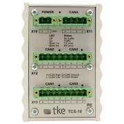
TKE TCS-10 CAN Switch
CAN switches are CAN network hardware devices that connect multiple CAN buses together. The connected CAN network segments are galvanically isolated to increase the robustness of the CAN network. The galvanic isolation eliminates the transmission of electrical disturbances between the network segments. Each galvanically separated network segment acts as a separate CAN bus. This enables different network segments to be run with different CAN bitrates. By altering the segment bitrate, the maximum length or bandwidth of the segment can be increased [1]. CAN switches function by retransmitting CAN frames between the CAN network segments. Error frames are not retransmitted between the segments to reduce bus load for the CAN network. Optionally, retransmission of CAN frames can be filtered to reduce unnecessary bus load. The retransmission filtering between network segments can be done globally for all segments or individually for different segments.
Topology improvements results.
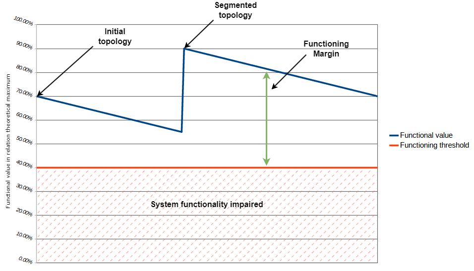
Based on the pre-study findings the control system CAN topology was changed to a segmented one. By changing the topology to a segmented one the functioning margin of the system was increased. As components in a system age the functioning margin of the system decreases. All systems contain a functioning threshold below which the system functionality is impaired. This notion is displayed in the figure below.

Figure 2: CAN network functioning margin
By increasing the system functioning margin the reliability and future-proofness of the system was increased. The system is more resistant against effects of system ageing and electromagnetic disturbances.
References
[1] S. Corrigan, “Controller Area Network Physical Layer Requirements”, Jan. 2008


