Experimental CANopen EEC management
Current CANopen design files do not support EECs (emergency error codes) with their human readable descriptions. This feature has become more problematic because of abstraction to parameters and signals. The system structure has become automated and proven way of working. Manual EEC management is decreasing the development efficiency because it is time-consuming and prone to inconsistent codes. These design projects are iterative and effort is wasted on each cycle of each project by managing EECs manually. Descriptions shall be uniformly defined for both producers and consumers.
This article shows how CANopen EECs (emergency error codes) can be described in EDS (electronic data sheet) and DCF (device configuration file) files and how EEC abstractions can be generated automatically for IEC 61131- 3 programmable devices from a CANopen project. CANopen design files contain device version information that enables to manage version-specific EECs. Codes are defined as global constants for emergency (EMCY) producers and a decoding function is generated for EMCY consumers. Centralized management enables definition of each code once in the producer’s EDS file and unlimited reuse of the codes.
The work made for this article is communicated to CiA TF (task force) XML to help defining the EEC decoding information into XML format XDD and XDC files, which will replace the current EDS and DCF files and provide some enhancements. Due to the standardized CANopen interfaces, EEC management is demonstrated with devices programmable in IEC 61131-3 structured text (ST), but programming language is not limited to it.
Source information
CANopen project is the source of information for all system integration information, including error codes with multilingual descriptions. Nodelist.cpj list the DCF files of each device in a project. Widely supported DCF and node list files are used in the experiments to enable the evaluation of EEC management in existing projects, where tool integration is used.
Standard entries exist for target position specific-information. Node-ID of each device is required in decoding because EECs with overlapping descriptions are not systematically prevented by CAN in Automation (CiA). NetworkName is used as a part of the export file name to support devices with multiple
CANopen interfaces. NetNumber is future reservation for remote EMCY decoding. An excerpt from a DCF file containing DeviceCommissioning section is presented in Figure 1. Experimental entries defining emergency error codes have been added to current EDS and DCF files to enable to prove the concept in real projects. Multiple languages can be supported for code descriptions. Same language codes with XDD and XDC are supported. The experimental extensions presented in Figure 2, are proposed as a part of the future XDD and XDC files. Entries NrOfLang and LangN can be used in determining the languages supported by EDS or DCF file. CodeN is a key for each EEC. Missing descriptions can be determined, when the language is supported for e.g. description in en-usN for code CodeN is missing. Number of supported codes is defined in NrOfCode. Entry LabelN is used as a name of a generated EEC constant for application-programmable EMCY producer. A short label needs to be entered manually because automatic name generation from description may result in ambiguous constant names. Comparable additional short labels are also defined in object attribute Denotation for remotely accessed parameters.
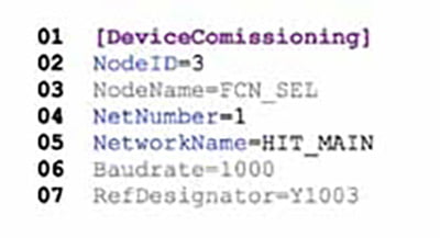
Figure 1: Example device commissioning section of a DCF file
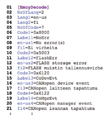
Figure 2: Example EEC description section for EDS and DCF files
Producer abstraction
Abstraction for EMCY producer is just a section of global constants, which is included in the same export with local parameter and signal abstractions. Constant definitions are located under section Global_ EEC_. Naming convention _ is used for constant names to support unique names for multiple network interfaces of a device. Constants can be used directly as EEC inputs for EMCY producer function block.Short labels
are needed because network name is added to the constant names and because of limited number of significant characters in variable names. Source file and conversion time are included as a comment line. An example abstraction for EMCY producer is shown in Figure 3.
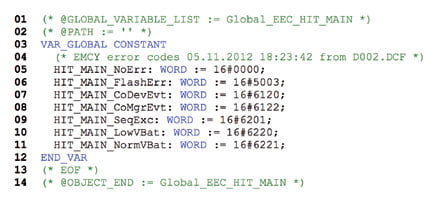
Figure 3: Example EEC abstraction for EMCY producer as Codesys 2.x export format
Collecting information
This section describes the phases of the error code and description collection process. The program structure is designed to enable further support of next generation XML format input and output files and integration into part of existing export tool.
Project file type is detected first. In addition to the standard nodelist.cpj project file, also a tool-specific nodelist.pco is supported. The automatic detection function first tries to access the standard file and if it is not found, it tries to read the proprietary file. It is assumed that the project files are located in the same folder with the DCF files of the project.
Project file parse functions are implemented in both supported formats. Those functions read the paths of the project’s DCF files. Nodelist.cpj lists DCF names without path and project path is added by the parse function. Absolute project path is used for DCFs in nodelist.pco and those paths are replaced with current project path to avoid a need for additional changes if project files are moved from one folder to another.
Information of nodes is read next. The values of standard entries Node-ID and NetworkName are used for producer identification. The experimental section is used for code to description mapping in specified language. Collection supports multiple languages and warnings are generated if the specified language is not supported or if a missing description is found for a code.
Information filtering and sorting follows parsing. If there are different descriptions for the same code used by different nodes, several decoding lists will be used. Filter function combines the non-over-lapping code – description value pairs and separates overlapping information into separate lists. If a second node introduces overlapping codes, all of its codes are stored into another decoding list.
Codes are sorted before exporting the decoding function. Ascending order of the EECs is used. Sorting may not be mandatory, but sorted codes in the decoding function help reading and possible troubleshooting.
Decoding function is generated in Codesys 2.x export file format as a last phase. Current output format is presented in details in section “error code decoding” of this article. The file output function is isolated so that PLCopen XML information transfer format support may be added later on as an option.
Executing the generator
Figure 4 presents an example of typical execution of the generator with required command-line options. First option indicates the path of the CANopen project – a folder, where either nodelist.cpj or nodelist. pco exists. Language selection for decoded code descriptions is selected by the second option. Supported language codes are adopted from XDD and XDC specification. Due to the DCF path replacement, dcf2emcy.py can read any CANopen project after folder changes and without any modifications to the project files.

Figure 4: Example console screenshot of generating EEC decoding function for EMCY consumer
Typically dcf2emcy.py is called from make-procedure or comparable batch execution mechanism of a project. Lines 7 to 8 indicate that two decoding lists were generated because of overlapping EECs. Output files are named as _ Language>. exp to enable the export of multiple language packets in the same batch. Target file example in Figure 5 is HIT_MAIN_enus. exp resulting from the conversion presented in Figure 4.
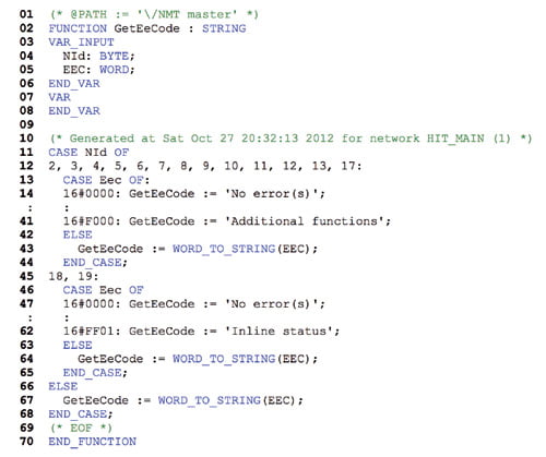
Figure 5: Example device commissioning section of a DCF file
Error code decoding
Error codes are decoded by a simple function. The example in Figure 5 presents how EECs produced by different node groups can be decoded differently. Inside the CASE-clauses, codes are sorted into ascending order based on the code values. EECs that are unknown or from undefined nodes are shown just as a raw decimal code values. Comment in line 1 indicates that the function is imported under NMT master group of project program organization units (POU). Comment in line 10 documents, from which file and when the information is exported. There is network-ID included at the end of the comment line to enable combining multiple decoding functions in the future.
Decoding function takes two arguments declared in lines 4 to 5 – producer node-ID and EEC of an event. CASE structures are used to keep the implementation simple. First, list size in bytes is limited in the PLCs, which would introduce problematic limits with list of visible strings. Second, code value range is large and only some codes are used – with lists, most of the items were unused but still reserving memory space.
Two levels are required, because different devices can use same codes differently. The outer CASE structure determines, which decoding list is used and for which nodes. The inner CASE structures in lines 13 to 44 and 46 to 65 decode the given EECs into corresponding descriptions. Due to the memory constraints of target device category, language selection is made during the design time, before compilation. For other kind of targets, run-time language selection may be used by e.g. adding one CASE level more for language selection.
Example event list utilizing an exported decoding list is presented in Figure 6. The example has been implemented in IEC 61131-3 programmable display. Event information is retrieved directly from standard CANopen EMCY consumer. Producer node names are retrieved from information exported for heartbeat consumer.
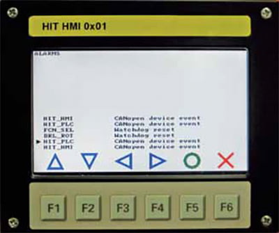
Figure 6: Example screenshot of event list with decoded codes in en-us
Results and outcome for experimental CANopen
When EEC decoding information is described already in EDS files, significant time saving is achieved. EEC decoding information collecting in single design iteration cycle cannot be improved, because supported codes with descriptions need to be searched from written manuals. Moreover, version management can be achieved for free, because EDS files include mandatory device version information. If same information were managed e.g. in spreadsheet, versions and languages still need to be managed manually. With e.g. spreadsheets, standardized links from device manufacturers to system integration and from system integration to software development are missing.
In the example project consisting of four types of devices with eleven codes in average, collection work from written manuals took approximately three work hours. Only English descriptions were included in manuals and Finnish descriptions were translated. After including the codes in an EDS file, they are usable in all projects using the same component.Execution time of the experimental collection routine is approximately 1 to 5 seconds, depending on the size and complexity of the project and the number of output languages. Execution can be linked as an integral part of the make process. Abstractions for EMCY producers are included as part of local interface export. The most significant result is that inconsistencies in EECs between producers and consumers were totally avoided despite of several revision cycles in each project.
Future work will concentrate on system-wide combining of EECs to support also remote EMCY decoding. It is already prepared by naming conventions. Also network number in parentheses at the end of comment line of the export supports future merging of the decoding functions. Other future area of interest is an option for producing multilingual decoding function. Final integration into current export tool may be performed after solving the system level collection. When EECs are included into EDS files, CANopen system design tools can improve troubleshooting by generating communication databases (DBC) with EEC decoding for CAN analyzer programs.


